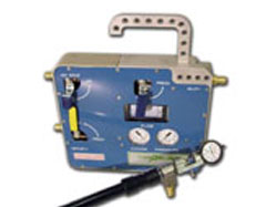
E-Probe - Equipo para inspección de motores alternativos

- Descripción
- Características
- Documentos
Descripción
E-Probe mide los componentes internos del motor tales como:
- Estado del cilindro de y desgaste - camisas, segmentos, puertos, cabeza y válvulas.
- Sumidero de la válvula y la configuración del tren
- Bulón de la muñequilla y juegos de biela (desgaste y tendencia)
- Tasas de fuga del cilindro
- Presión de los gases en el carter
Diseñado para motores partidos de alta velocidad y monoloque de baja velocidad, DynaProbe trabaja para que pueda llevar a cabo precisas inspecciones de motores (sin desmontaje del motor) más seguras, más rápidamente, más fácil y de una manera más limpia.
E-Probe reduce significativamente los costos de mantenimiento al reducir el tiempo de inspección y sobre todo, reduce los gastos en mantenimientos programados que aconsejan la sustitución indiscriminada de piezas, incluso aunque se encuentren en buen estado.
Las mediciones de precisión se toman mediante la instalación de la sonda en el alojamiento de la bujía, del inyector de combustible, o en la parte inferior del cilindro. Al inyectar aire a presión, en el cilindro se determinar la condición de los segmentos, camisa y válvulas. Mediante la aplicación de un vacío, se mide el desgaste de la biela y el desgaste de los cojinetes de las muñequillas.
Características
DynaProbe Componet Parts
Manifold Assembly
The Manifold Assembly houses valves that control the routing of air through the system and valves that control the amount of air flowing through the system.
Regulator/Filter Assembly
The Filter/Regulator Assembly filters and regulates the air supply at a constant 80 psi to the DynaProbe System.
Probe with Dial Indicator
The probe is inserted into the spark plug hole. The probe tip and stylus are mounted on the end of the probe.
Probe Tips
Probe tips ensure that the Probe Stylus (see Probe Stylus) is exactly perpendicular to the piston face. Probe Tips come in different lengths and angles. Probe Tips screw onto the Probe.
Probe Stylus
The Probe Stylus is inserted in the Probe Tip and is used to measure bearing clearances.
Hose A
40 ft. with a 3/4" diameter hose with 3/4" NPT crows foot to 3/4" NPT crows foot. Hose A connects to the station supply and to the Filter Regulator Assembly.
Hose B
40 ft. with a 3/4" diameter hose with 1/2" NPT QD male to 1/2" NPT QD female. Hose B connects the Filter Regulator Assembly to the Manifold Assembly.
Hose C
5 ft. with a 3/4" diameter hose with 1/2" NPT QD female to 1/2" NPT QD female. Hose C connects the Manifold Assembly to the Probe Body.
Hose D
25 ft. with a 3/4" diameter hose with 1/2" NPT QD female to 1/2" NPT QD male. Hose D connects the Manifold Assembly to the Auxiliary Venturi.
Optional Items
Universal Adapter Kit
The Universal Adapter Kit is used to install the probe through the fuel injector opening.
Auxiliary Venturi/Auxiliary Venturi Adapter
The Auxiliary Venturi and Adapter are used when making a master rod bearing check on an articulated engine.
 PREDITEC - IRM, Your partner in reliability


